Birmingham Resilience – 2.44 dia Tunnel
About This Project
The £242m Birmingham Resilience Project is one of Severn Trent Water’s most ambitious capital projects yet, the goal of which is to provide an alternative water supply for Britain’s second city.
The project aims to deliver a new water supply into Birmingham to allow extended planned maintenance shutdowns of the Elan Valley Aqueduct (as well as providing a back-up for any emergency events) and to strengthen the treatment processes at Frankley WTW. This will require a new treatment process capable of treating 237Ml/day +/- 40Ml/d for diurnal variation.
Challenges and Solutions…
The site (specifically the location of the tunnel as outlined below) is adjacent to the existing Frankley Reservoir and is overseen by a Reservoir Panel Engineer. The line of the tunnel came with 25m of the reservoir wall and 10m of the supporting embankment. Both the tunnel construction and the excavation/forming of the cofferdam reception pit were subjected to a 5mm/s vibration limit, monitored via equidistant vibration & tilt monitors along the length of the tunnel and the South Tower structure (construction date of 1896) itself. Each design decision, risk assessment, method statements and programme had to be sanctioned by the supervising Panel Engineer which required significant collaboration between the various contractors, Severn Trent & the Panel Engineers themselves.
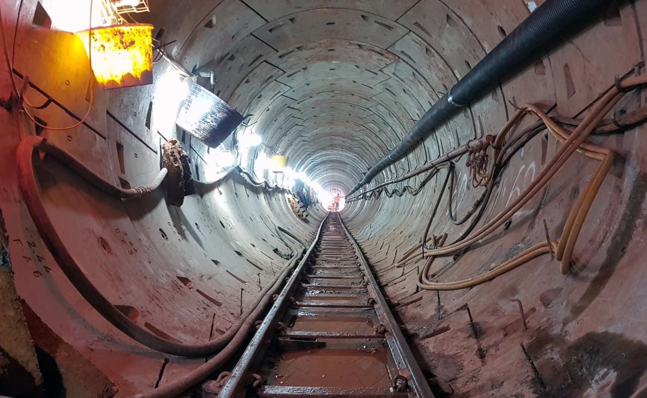
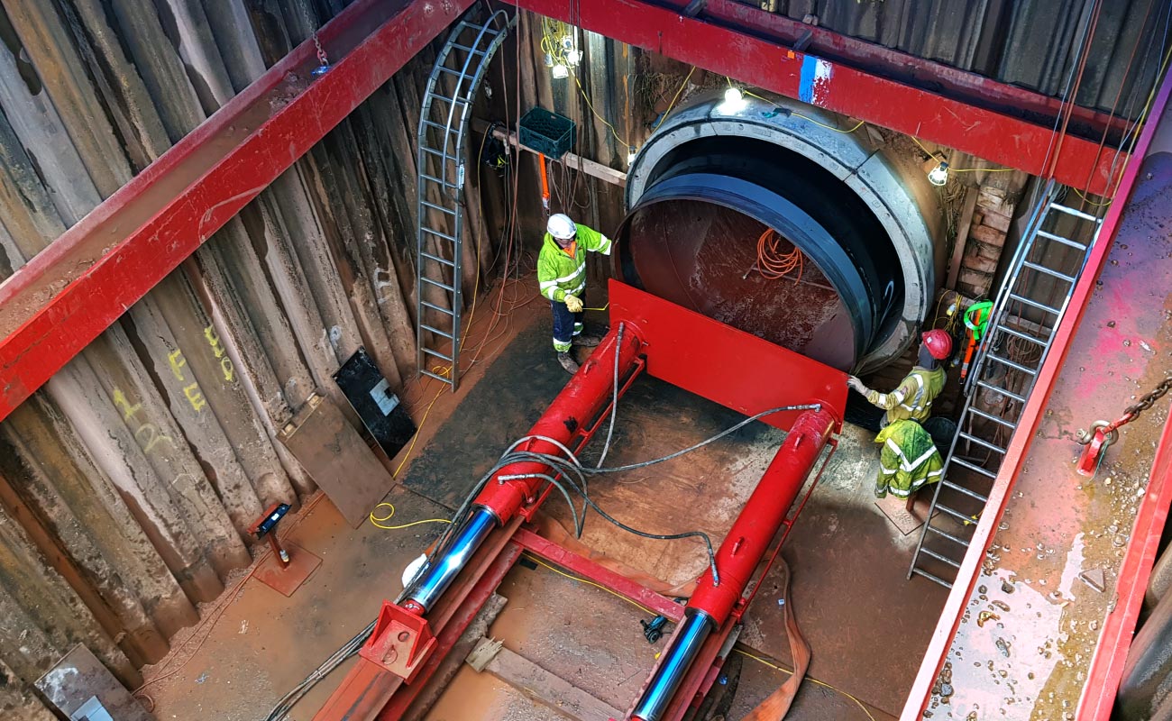
Part of the project requires an ability to convey water from the Reservoirs South Draw-off Tower to the Sand Ballasted Lamella’s inlet arrangement. The outlet manifold, 12.5m below ex. GL, will connect to 3 No. existing (blanked flange) outlets. Due to the access depth and proximity/sensitivity of the adjacent Frankley Reservoir, a tunnel solution was formed in which a 2200mm diameter spiral welded steel pipe was to be installed.
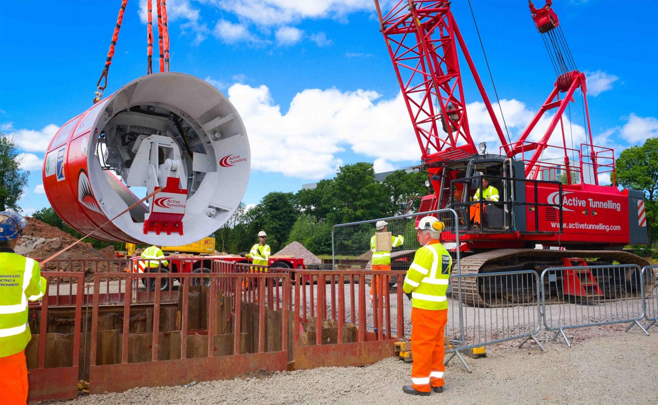
The availability of TBM’s within the allotted programme drove the selection of a 2440mm NB open-faced Backactor TBM. The available machine meant that tolerances were tight for sleeving the steel pipe within the tunnel lining.The steel pipe manufacturing tolerance of 1.6mm along with potential ovalisation of 2%,the grout lines, guide rail and a protective plastic shoe on each joint, coupled with the manufacturing tolerance of the segmental rings (1% < 50mm) & construction tolerance, left only 22mm between the steel pipe and the tunnel lining.
To mitigate the risk of the pipe “sleeve” becoming wedged within the tunnel, a number of proactive initiatives were utilised. Each of the 25 No. 22mm wall thick steel pipes were scanned at the source mill in Spain by a 3rd party surveyor. This provided the team with a 3d heat map of each pipe, allowing each pipe to be rotated such that the greatest tolerance defect was located (within the tunnel) at the least point of interference (horizontal axis). The pipes were transported within individual containers from Spain to the UK and, again, re-scanned upon site arrival. Toughened plastic sheets were imported from Holland and moulded to the pipe at our HQ to ensure minimum friction between the pipe and the rail, as well as protecting the outer coating of the pipe. The shoes had to be fixed via band straps to the pipe to ensure no movement during the jacking operation.
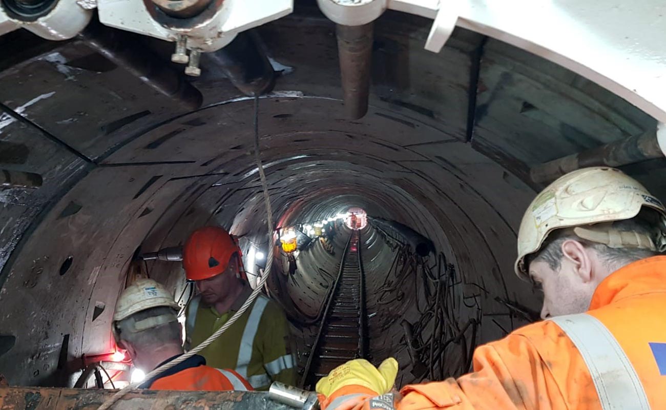
The tunnel construction was overseen by 3 No. on-site engineers with each segment being subject to a post install ITF (inspection & test form). The segment deviation was limited to +/- 10mm and benchmarked from the drive pit. The tunnel, in its entirety, was accurate to 10mm over the 197m long drive length.
Client:
STW
Location:
Birmingham
Value:
£1.5m
Duration
10 Months